Structural Steel Alignment Checklist Template: Your Guide to Precision
Published: 09/02/2025 Updated: 05/28/2026
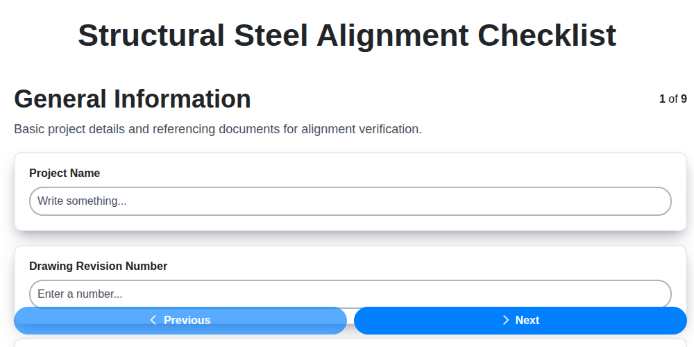
Table of Contents
- Introduction: Why Precise Steel Alignment Matters
- Understanding Structural Steel Alignment Tolerances
- The Comprehensive Structural Steel Alignment Checklist
- Section 1: Foundation and Base Plate Verification
- Section 2: Column Alignment - Ensuring Verticality
- Section 3: Beam Alignment - Achieving Level Precision
- Section 4: Connection Alignment - Bolted & Welded Integrity
- Section 5: Bracing Alignment - Stability and Load Distribution
- Section 6: Roof Truss & Frame Alignment - Maintaining Geometry
- Section 7: Girder & Main Beam Alignment - Long-Span Accuracy
- Section 8: As-Built Documentation - Recording the Reality
- Common Alignment Challenges & Troubleshooting Tips
- Leveraging Technology for Enhanced Accuracy (BIM, Laser Scanners)
- Safety First: Best Practices for Steel Alignment
- Download Your Free Structural Steel Alignment Checklist Template!
- Resources & Links
TLDR: Need to ensure your structural steel erection is accurate and compliant? This checklist template provides a step-by-step guide, covering everything from foundation alignment to as-built verification. Download it to streamline your process, minimize errors, and guarantee a structurally sound build - saving time and money in the long run.
Introduction: Why Precise Steel Alignment Matters
Structural steel forms the backbone of countless buildings and infrastructure projects, supporting immense loads and enduring environmental stresses. While the strength of the steel itself is paramount, its effectiveness is entirely dependent on how precisely it's assembled. Imagine a meticulously designed puzzle - even slight misalignments between pieces can compromise the entire structure's integrity. This isn's just about aesthetics; it's about ensuring load transfer is efficient, connections are strong, and the building behaves as intended under all conditions. Poor alignment can lead to increased stress on individual members, potential for premature failure, costly rework, and ultimately, a structure that doesn't perform to its design specifications. Investing in careful alignment processes upfront is a critical investment in the long-term safety, stability, and functionality of any steel-framed project.
Understanding Structural Steel Alignment Tolerances
So, you've grasped the what and why of structural steel alignment - but what about the how much? This is where tolerances come into play. Alignment tolerances define the permissible deviation from perfect alignment, recognizing that achieving absolute perfection in the field is often impractical and, frankly, unnecessary.
Think of tolerances as a range of acceptability. A tolerance of ± 1/8 inch per 10 feet of column height, for instance, allows for up to 1/8 inch of deviation from perfectly plumb for every 10 feet of column height. Exceeding that tolerance triggers corrective action.
Why Aren't Tolerances Zero?
Several factors contribute to the need for tolerances:
- Fabrication Variations: Steel plates have slight variations in thickness and dimensions due to the manufacturing process.
- Erection Challenges: Site conditions, equipment limitations, and human error inevitably introduce small deviations during erection.
- Cost-Benefit Analysis: Achieving tighter tolerances requires increased labor, specialized equipment, and potentially more costly correction methods. A balance must be struck between alignment precision and overall project cost.
- Structural Redundancy: Well-designed steel structures possess inherent redundancy, meaning they can still safely withstand loads even with minor misalignments within the specified tolerances.
Types of Tolerances
Tolerances aren't a one-size-fits-all concept. They vary depending on the structural element and its function. Common examples include:
- Plumbness Tolerances: Allowable deviation from vertical for columns and other vertical members.
- Levelness Tolerances: Allowable deviation from horizontal for beams and decks.
- Rotation Tolerances: Allowable angular deviation between connected members.
- Linear Alignment Tolerances: Allowable deviation from a straight line for beams or tracks.
Where to Find Tolerances
Structural steel alignment tolerances are always defined in the project's structural drawings and specifications. These documents are the definitive source for acceptable deviations and should be carefully reviewed by all involved parties before erection begins. Don't rely on assumptions or general rules of thumb. The contract documents rule.
The Comprehensive Structural Steel Alignment Checklist
Simply eyeballing alignment isn's good enough-it's a recipe for costly rework, compromised structural integrity, and potential safety hazards. A comprehensive checklist isn't just a formality; it's a vital tool for ensuring accuracy and accountability throughout the steel erection process. It provides a standardized process, minimizes errors, and serves as a crucial record of verification.
Think of it as your blueprint for precision. Each item on the checklist represents a critical aspect of the alignment process, guiding the erector and inspector to systematically verify compliance with the design specifications. Skipping steps or relying on subjective assessments can lead to subtle deviations that accumulate and significantly impact the overall performance of the structure.
A well-structured checklist promotes clear communication among all stakeholders - the structural engineer, erector, surveyor, and inspector - fostering a collaborative approach to achieving the desired level of accuracy. It provides a common language and a shared understanding of the required outcomes, reducing the potential for misunderstandings and ensuring everyone is on the same page. Beyond the immediate erection phase, the completed checklist serves as a valuable reference for future maintenance, repairs, or modifications to the structure.
Section 1: Foundation and Base Plate Verification
A structurally sound foundation is the bedrock of any steel building. Any deviation here will cascade through the entire erection process, creating alignment headaches and potential instability. Thorough verification of the foundation and base plates is therefore the crucial first step.
1.1 Levelness Assessment: The foundation's levelness is paramount. Use a level or total station to meticulously check the top of the foundation concrete. Record any high or low spots and their deviations from the designed elevation. Significant variations (exceeding project-defined tolerances) may necessitate grinding or shimming to achieve a perfectly level surface.
1.2 Base Plate Location and Offset: Precisely locate each base plate according to the structural drawings, paying close attention to the established offset dimensions. Confirm that the base plate's position accurately reflects the intended column location. Even minor discrepancies can affect overall structural integrity.
1.3 Anchor Bolt Integrity: Verify the position, size, and condition of each anchor bolt. Anchor bolts are vital for securing the steel columns to the concrete foundation. Check for:
- Correct Spacing: Confirm that anchor bolt spacing matches the design specifications.
- Embedment Depth: Ensure the bolts are properly embedded in the concrete.
- Corrosion or Damage: Inspect for signs of corrosion or physical damage. Damaged anchor bolts must be replaced.
- Accessibility: Ensure sufficient clearance around the anchor bolts for proper bolting operations.
1.4 Base Plate Squareness: Base plate squareness relative to the foundation is critical for plumb column alignment. Use a square or angle finder to verify the base plate's orientation. Correct any angular misalignment before proceeding. This step ensures a stable and properly aligned column.
1.5 Concrete Curing: Visually inspect the concrete for proper curing. Cracks or inconsistencies can affect anchor bolt performance and overall foundation stability. Document any concerns and consult with the project engineer.
Section 2: Column Alignment - Ensuring Verticality
Columns form the backbone of any steel structure, and their precise verticality is paramount for load transfer and overall stability. Even slight deviations from plumb can compound over height, leading to significant issues with subsequent steel erection and potentially compromising the entire building's integrity. A thorough column alignment process is, therefore, non-negotiable.
The first step involves a visual inspection to identify any immediately obvious issues, such as leaning or twisting. Following this, several methods can be employed to verify column plumbness. Traditional techniques utilizing plumb bobs remain reliable and cost-effective for smaller projects. However, for larger or more complex structures, laser levels and total stations offer superior accuracy and efficiency. These tools project a level plane or establish a vertical reference line, allowing for precise measurement of deviations.
Alignment is typically assessed at multiple points along the column's height - at the base, midpoint, and top. Any observed discrepancies must be carefully documented and addressed. Minor deviations can often be corrected by shimming the base plate or using temporary bracing. However, larger discrepancies may indicate underlying issues with the foundation or require more extensive corrective measures. Remember to continuously monitor column alignment throughout the erection process, especially after any adjustments are made. Proper bracing techniques are critical during this phase to maintain column stability and prevent re-deviation. Document all adjustments meticulously, noting the method used and the resulting correction.
Section 3: Beam Alignment - Achieving Level Precision
Achieving accurate beam alignment is paramount, and it's often more challenging than it initially appears. While seemingly straightforward, even slight deviations from level can cascade into larger issues with connection integrity, roof drainage, and overall structural performance. This section delves into the nuances of beam alignment, outlining best practices for achieving that critical level precision.
First, it's crucial to understand that 'level' isn't always a static concept. Sloped beams, for example, require a different approach - verifying they match the design slope angle rather than being perfectly horizontal. Regardless of the design, several techniques ensure accuracy.
Tools of the Trade: Traditional levels, while useful for smaller spans, struggle with larger beams and uneven surfaces. Laser levels and rotating beams offer significantly improved precision and visibility. Total stations and 3D laser scanners provide comprehensive data for complex projects, allowing for detailed analysis and adjustments. Don't forget the trusty plumb bob for spot-checking.
Addressing Common Challenges:
- Uneven Bearing Points: Uneven foundation or supporting elements can make achieving level difficult. Shim plates are your friend. Carefully measure and gradually add shims until the beam is perfectly level.
- Beam Deflection: Newly erected beams will naturally deflect under their own weight. Account for this deflection in your alignment calculations. Re-check the alignment after a period of time to confirm stability.
- Wind Load: Wind can exert significant force on beams during erection, making alignment more difficult. Secure beams properly and wait for calmer conditions.
Verification is Key: Never assume a beam is level simply because the initial alignment appears correct. Multiple checks with different tools and techniques are essential to confirm accuracy. Document all measurements and adjustments meticulously. A second set of eyes always helps - have another experienced team member verify your findings.
Section 4: Connection Alignment - Bolted & Welded Integrity
Connections are the backbone of any steel structure, transferring loads between members and dictating overall stability. A perfectly aligned frame is useless if the connections fail. Therefore, meticulous connection alignment - both bolted and welded - is paramount. This section delves into the critical steps for ensuring connection integrity.
Bolted Connections: Precision is Key
Bolted connections rely on precise hole alignment to guarantee proper bolt engagement and clamping force. Deviations can lead to stress concentrations and weakened connections. Here's what to check:
- Bolt Hole Alignment: Using alignment plates or jigs is often necessary to ensure accurate hole alignment before bolt insertion. Check for parallelism between bolt holes and the member's face. Misalignment can compromise bolt tensioning.
- Edge Distance & Pitch: Verify edge distances and bolt spacing meet the design specifications. Inadequate spacing can lead to bolt interference or reduced connection strength.
- Bolt Tensioning: Employing proper torqueing procedures is crucial. Use calibrated torque wrenches and follow the manufacturer's recommendations for lubrication and tightening sequence. Monitor bolt elongation to confirm sufficient clamping force.
- Visual Inspection: After tightening, visually inspect the bolt heads and nuts for any signs of damage or distortion.
Welded Connections: Fit-Up & Alignment are Crucial
Welded connections require even greater attention to detail. Proper fit-up and alignment are absolutely critical for a sound weld. Poor fit-up leads to gaps and incomplete fusion, significantly reducing the connection's strength.
- Fit-Up Verification: Carefully check the fit-up between members to be welded. Gaps exceeding allowable tolerances should be corrected before welding commences.
- Edge Preparation: Ensure proper edge preparation (beveling, cleaning) has been performed as specified in the welding procedures.
- Alignment During Welding: Maintain accurate alignment during the welding process. Use temporary bracing or jigs to prevent movement and distortion.
- Welder Certification & Procedure: Verify that the welders are properly certified for the specified welding process and that they adhere to approved welding procedures. Inspect welds visually for defects such as porosity, cracks, and incomplete fusion. Non-destructive testing (NDT) methods, like ultrasonic testing or radiography, may be required for critical connections.
Section 5: Bracing Alignment - Stability and Load Distribution
Bracing plays a crucial role in resisting lateral forces like wind and seismic loads, ensuring the overall stability of the structure and distributing loads effectively. Proper bracing alignment isn't just about aesthetics; it's about guaranteeing the structural integrity of the entire building.
Here's what to verify during bracing alignment:
- Plumbness/Levelness: Using levels, plumb bobs, or laser alignment tools, meticulously check each bracing member for vertical (plumbness) and horizontal (levelness) alignment. Even slight deviations can compromise bracing effectiveness.
- Diagonal Angle: Bracing members are installed at specific angles to resist lateral forces. Verify that these angles precisely match the design specifications. Incorrect angles will significantly reduce the bracing's capacity.
- Connection Alignment (Bracing): Just like with general connections, bracing connections - whether bolted or welded - must be perfectly aligned. Misaligned connections weaken the bracing's ability to transfer forces, creating a potential failure point. Double-check bolt hole alignment before bolting and ensure proper fit-up before welding.
- Tension and Compression Checks: For X-braces, confirm that one member is in tension and the other in compression as designed. Misalignment can reverse this, significantly reducing stability.
- Continuous Checks: Don't just check individual bracing members in isolation. Verify the continuous alignment of bracing systems across multiple bays to ensure seamless load transfer.
A dedicated inspection and re-inspection of bracing alignment throughout the erection process is paramount for long-term structural safety.
Section 6: Roof Truss & Frame Alignment - Maintaining Geometry
Roof trusses and frames are critical for the structural integrity and aesthetic appeal of a building. Maintaining their intended geometry throughout the erection process is paramount. Unlike simpler beam alignments, roof trusses and frames often involve complex angles, intricate bracing patterns, and significant spans, making precise alignment even more crucial.
The primary focus here is verifying the overall geometry - ensuring the roof doesn't resemble a distorted version of the design. Begin by confirming the chord alignment; top and bottom chords must be perfectly straight and parallel to the design lines. Any deviation here can lead to uneven load distribution and potential failure. Next, meticulously examine the web member alignment. These diagonal and vertical members play a vital role in transferring loads, and even slight misalignments can compromise their effectiveness.
Special attention should be paid to the connections between truss members. Bolted or welded connections must be executed with pinpoint accuracy. Use alignment jigs or fixtures where necessary to ensure perfect fit-up. Consider using a total station or laser scanner to capture a complete 3D profile of the installed truss/frame, allowing for a quick comparison with the design model. Any discrepancies should be immediately addressed and documented. Furthermore, thoroughly check the bracing patterns within the truss/frame. These bracing members contribute significantly to the overall rigidity and stability of the roof system; their alignment is non-negotiable. Finally, always remember to account for any anticipated settlement or deflection, especially with large-span trusses. Properly aligned trusses and frames contribute to a structurally sound and visually appealing roof - meticulous attention to detail is key.
Section 7: Girder & Main Beam Alignment - Long-Span Accuracy
Girder and main beam alignment demands a heightened level of precision compared to smaller structural elements. Their significant spans and crucial role in load distribution necessitate meticulous attention to detail to prevent excessive deflection, stress concentrations, and potential instability. The potential for issues escalates dramatically with longer spans, making a rigorous alignment process absolutely vital.
Beyond Levelness: Sag Verification & Rotation Control
While ensuring levelness remains paramount, the focus shifts to verifying the sag of the girder or main beam. Design calculations determine the allowable sag under specified loads; it's critical to confirm the actual deflection falls within those limits. This often involves using surveying equipment to measure the beam's profile along its entire length and comparing the results to the design specifications. Slight variations can indicate issues with material properties, connection tightness, or foundation settlement.
Rotation control is another critical aspect. Even small rotational deviations can introduce significant stresses and affect the overall structural integrity. Careful monitoring and adjustment of connections, particularly at the supports, are crucial to minimize rotation. Temporary bracing may be required during the alignment process to maintain the desired geometry.
Specialized Equipment & Techniques
Aligning long-span girders and main beams frequently requires specialized equipment and techniques:
- Laser Measurement Systems: Provide highly accurate measurements over long distances.
- Multi-Point Leveling: Enables comprehensive assessment of beam profile.
- Adjustable Supports: Allow for fine-tuning of the beam's position and elevation.
- Tensioning & Jacking: May be necessary to achieve precise alignment and counteract forces.
The Domino Effect: Foundation Monitoring
It's essential to remember that long-span girder alignment is often linked to foundation stability. Any signs of settlement or movement in the supporting foundations can directly impact the beam's geometry. Regular monitoring of the foundation's elevation and stability is a proactive measure that can prevent costly realignment or even structural failure.
Section 8: As-Built Documentation - Recording the Reality
The alignment process isn't just about getting things straight; it's about preserving that achieved accuracy for the future. As-built documentation is the critical bridge between the theoretical design and the actual, constructed reality. It's more than just a formality; it's a vital record for maintenance, renovations, and any future modifications to the structure.
Think of it this way: the original design drawings are a blueprint. The as-built drawings are the updated map reflecting the terrain after construction. Without it, future engineers and maintenance crews are navigating with outdated information, increasing the risk of errors and inefficiencies.
What Needs to Be Recorded?
Beyond just noting dimensional corrections, comprehensive as-built documentation should include:
- Dimensional Deviations: Meticulously record the actual field dimensions of all aligned elements, compared to the original design.
- Adjustment Details: Precisely document how and why adjustments were made. This includes the methods used (e.g., shimming, grinding, re-welding) and the personnel involved.
- Material Changes: If any substitutions were made to materials (e.g., different grade of bolt, different manufacturer), clearly note these changes and the reason for the substitution.
- Connection Modifications: Any alterations to connection details - weld sizes, bolt patterns, etc. - must be accurately reflected.
- Location of Hidden Elements: If any unforeseen elements were encountered during the alignment process (e.g., buried utilities, existing obstructions), their location should be recorded.
- Photographic Evidence: Supplement the drawings with photographs illustrating the final aligned condition and any significant modifications made. These provide a visual record that can be invaluable for future reference.
The Long-Term Value:
Investing in thorough as-built documentation isn't just about compliance; it's an investment in the long-term health and usability of the structure. It minimizes risks, streamlines future maintenance, and ensures that any modifications are implemented safely and efficiently. Think of it as leaving a clear and accurate roadmap for generations to come.
Common Alignment Challenges & Troubleshooting Tips
Even with meticulous planning and a comprehensive checklist, unexpected challenges can arise during structural steel alignment. Here's a look at frequently encountered issues and practical troubleshooting tips:
1. Unstable Foundations: Foundation settlement or inconsistencies in levelness are primary culprits.
- Troubleshooting: Re-verify foundation elevations against design documents. Consider temporary shims or adjustments to base plates. Consult a geotechnical engineer if significant settlement occurs. Accurate records of any corrections are vital.
2. Anchor Bolt Problems: Bent, sheared, or incorrectly positioned anchor bolts can derail alignment efforts.
- Troubleshooting: Replace damaged anchor bolts immediately. Use alignment fixtures to compensate for slight anchor bolt variations. Confirm bolt embedment depth meets specifications.
3. Column Kick-Out: This refers to a column that isn't perfectly plumb and has visibly bowed or leaned.
- Troubleshooting: Utilize jacks and shims strategically to correct the column's verticality. Re-check plumbness frequently throughout the adjustment process. Investigate the cause (e.g., improper lifting techniques) to prevent recurrence.
4. Beam Deflection Beyond Tolerance: Beams might deflect more than anticipated under temporary loads or due to material inconsistencies.
- Troubleshooting: Temporarily support the beam using shoring to allow for adjustments. Verify beam material properties match design specifications. Recalculate deflection and potentially adjust support locations.
5. Connection Fit-Up Issues: Difficulties aligning bolt holes or weld seams can significantly slow down the erection process.
- Troubleshooting: Use heat to slightly expand the steel, facilitating bolt insertion. Employ temporary clamping devices to hold pieces in place during welding. Conduct a thorough inspection before proceeding to the next step.
6. Temporary Bracing Interference: Temporary bracing can sometimes impede alignment adjustments.
- Troubleshooting: Carefully analyze the bracing's impact on alignment possibilities. Modify or temporarily remove bracing, ensuring structural stability is maintained.
7. Material Inconsistencies: Variations in steel dimensions or stiffness can cause alignment discrepancies.
- Troubleshooting: Conduct thorough material verification checks to ensure compliance with specifications. Communicate any discrepancies to the supplier and engineer.
Remember, proactive communication and a flexible approach are essential for overcoming alignment challenges and ensuring a successful project. Don't hesitate to consult with structural engineers or experienced erectors when facing difficult situations.
Leveraging Technology for Enhanced Accuracy (BIM, Laser Scanners)
The structural steel erection industry is rapidly evolving, and embracing technology is no longer a luxury - it's a necessity for achieving superior accuracy and efficiency. Traditional methods, while reliable, often rely on manual measurements and visual inspections, which are inherently susceptible to human error. Fortunately, innovative tools are readily available to mitigate these risks and streamline the process.
Building Information Modeling (BIM): A Virtual Blueprint
BIM isn't just a 3D model; it's a collaborative platform that integrates design, fabrication, and erection data. By leveraging BIM, erectors can clash-detect potential conflicts before steel arrives on site, minimizing costly rework. Moreover, BIM provides a virtual representation of the structure, allowing for detailed planning and sequencing of erection activities. The ability to virtually walk the structure and identify potential challenges significantly reduces on-site surprises.
Laser Scanning: Capturing Reality with Precision
High-resolution laser scanners offer a revolutionary approach to alignment verification. These devices rapidly capture a point cloud representation of the existing conditions, providing a highly accurate digital twin of the foundation, columns, and other critical elements. This data can then be compared directly to the BIM model or design drawings, revealing even subtle misalignments that might be missed by traditional methods. The resulting point cloud data can be used to generate as-built drawings and to assist with the development of adjustment plans. Furthermore, laser scanning can be used for progressive monitoring of the structure during erection, providing a record of the process. Combining laser scanning with BIM allows for automated comparison and precise determination of adjustments needed.
The adoption of these technologies not only improves accuracy but also enhances communication, reduces project timelines, and ultimately contributes to a safer and more cost-effective erection process.
Safety First: Best Practices for Steel Alignment
Steel alignment isn't just about precision; it's inherently a hazardous activity. Working at height, using heavy equipment, and dealing with potentially unstable structures demand a rigorous safety-first approach. Here's how to prioritize safety while ensuring accurate alignment:
1. Comprehensive Risk Assessment: Before any alignment work begins, conduct a thorough risk assessment. Identify potential hazards - falls, struck-by objects, equipment malfunctions - and implement appropriate control measures. This assessment should be documented and reviewed regularly.
2. Fall Protection is Non-Negotiable: Working on steel structures invariably involves working at height. Utilize appropriate fall protection equipment - harnesses, lanyards, lifelines - and ensure all personnel are properly trained in its use and inspection. Guardrails and other passive fall protection systems should be used whenever possible.
3. Rigging Expertise & Inspections: Proper rigging techniques are crucial for safely lifting and positioning steel members. Ensure all rigging personnel are certified and experienced. Inspect all rigging equipment (slings, shackles, chains) before each use and remove any damaged items from service.
4. Equipment Operation & Safe Zones: Cranes, levels, and other alignment equipment must be operated by trained and certified personnel. Establish clear and well-marked safe zones around operating equipment to prevent accidental contact. Communication protocols between crane operators and ground personnel are essential.
5. Structural Stability & Temporary Bracing: Alignment adjustments can temporarily destabilize the structure. Ensure proper temporary bracing is in place to prevent collapses or shifting. A qualified engineer should assess the need for temporary bracing and approve the bracing plan.
6. Personal Protective Equipment (PPE): All personnel involved in steel alignment should wear appropriate PPE, including hard hats, safety glasses, high-visibility clothing, and steel-toed boots.
7. Communication & Coordination: Clear and consistent communication is vital. Use hand signals, radios, or other reliable means to communicate instructions and warnings. Coordinate activities between all teams involved.
8. Weather Considerations: Adverse weather conditions (high winds, rain, ice) can significantly increase the risk of accidents. Postpone alignment work if weather conditions are unsafe.
Remember, a proactive safety culture is everyone's responsibility. Prioritize safety, follow procedures, and ensure everyone goes home safe at the end of the day.
Download Your Free Structural Steel Alignment Checklist Template!
Ready to streamline your structural steel alignment process and ensure project integrity? We're giving away a fully customizable checklist template designed to be your go-to guide for meticulous alignment verification.
This isn't just a list; it's a structured framework, incorporating key areas like foundation checks, column plumbness, beam levelness, connection integrity, and as-built documentation. Simply download the template, fill in your project-specific tolerances and drawing references, and print it for easy field use.
What you're getting:
- A comprehensive checklist covering all critical alignment stages.
- Ready-to-use sections for general information, inspection details, and adjustments.
- A professional starting point - easily adaptable to your specific project needs.
Resources & Links
- American Institute of Steel Construction (AISC) : The leading authority and resource for steel construction, providing standards, specifications, and best practices for structural steel design, fabrication, and erection. Crucial for understanding steel construction principles and tolerances. Specifically, refer to AISC 360 (Specification for Structural Steel Buildings).
- American National Standards Institute (ANSI) : ANSI coordinates the development of voluntary consensus standards in the United States. Steel alignment often falls under broader construction standards developed or referenced by ANSI. Look for standards related to dimensional control and tolerances.
- Building Science Corporation : While not directly focused on steel alignment, Building Science provides valuable information on the impact of building geometry and tolerances on building performance and envelope integrity, relevant when considering steel alignment's long-term implications.
- Trimble : A leading provider of construction technology solutions, including laser scanners, total stations, and BIM software, which are vital for precise steel alignment verification and documentation. Their website details products and applications in the structural steel industry.
- Leica Geosystems : Another key provider of surveying and measurement instruments, including laser scanners and total stations. They offer tools and solutions that are essential for achieving and verifying precise steel alignment. Explore their solutions for construction and surveying.
- Autodesk : Provides BIM (Building Information Modeling) software like Revit, instrumental in planning, designing, and coordinating steel structures. BIM models facilitate clash detection and accurate alignment planning. Review their construction solutions.
- Bentley Systems : A global leader in engineering software, offering solutions for infrastructure design and construction, including structural steel design and analysis. Their products often integrate with surveying and laser scanning data.
- Hexagon : Offers a broad portfolio of technologies including laser scanning, measurement automation, and quality management tools. Their solutions are applied throughout the structural steel fabrication and erection processes.
- Stamford Steel : A fabrication company's website can provide insights into common alignment challenges and best practices from a fabrication perspective. This helps understand what to anticipate during the alignment process.
- Bureau of Land Management (BLM) : While primarily focused on public lands, the BLM's surveying and mapping techniques and standards are relevant to dimensional control and accuracy. Their guidelines can be helpful when extreme precision is required.
Frequently Asked Questions
What is a structural steel alignment checklist and why is it important?
A structural steel alignment checklist is a document used to verify that structural steel components are installed according to approved plans and tolerances. It's crucial for ensuring the building's structural integrity, functionality, and aesthetic appeal, preventing issues like uneven loads, difficulty in connecting subsequent elements, and costly rework.
Who should use this checklist template?
This template is designed for various stakeholders involved in structural steel erection, including steel erectors, field supervisors, quality control inspectors, and project engineers. Anyone responsible for verifying steel alignment can benefit from using this checklist.
What information do I need before using the checklist template?
You'll need the approved structural drawings (shop drawings and erection plans), specifications, and a clear understanding of the project's tolerance requirements. It's also helpful to have a recent survey to compare against.
How do I customize the template to fit my project?
The template is designed to be flexible. You can add or remove items specific to your project's scope, adjust tolerances as needed (according to project specifications), and add specific equipment or details relevant to the steel members being installed. Adding project-specific notes and photographs is also recommended.
What does 'tolerance' mean in the context of steel alignment?
Tolerance refers to the allowable deviation from the specified location or dimension of a structural steel member. It's the acceptable margin of error. Project specifications will define these tolerances - typically expressed in inches or millimeters.
What happens if a structural steel member is out of alignment?
If a member is found to be out of alignment, the erector must correct the issue before proceeding. The discrepancy should be documented and reviewed by the project engineer. A Request for Information (RFI) might be necessary depending on the severity of the deviation.
Can this checklist be used for all types of structural steel projects?
While the template is broadly applicable, complex or highly specialized projects (like bridges or skyscrapers) might require a more detailed and customized checklist. Always review and adjust the template to match the project's unique requirements.
What's the difference between 'level' and 'plumb'?
'Level' means horizontally aligned with a reference plane, usually the established datum. 'Plumb' means vertically aligned, perpendicular to the ground (or a designated vertical reference).
How should I document discrepancies found during the alignment check?
Document all discrepancies with detailed descriptions, photographs, and location identifiers. Record the corrective actions taken and the personnel responsible for the correction. A formal log or digital platform for tracking these issues is recommended.
Where can I find the project's tolerance specifications?
The tolerance specifications are typically found in the project's structural drawings, specifications, and contract documents. Always refer to the official project documentation for definitive values.
Found this Article helpful?
Construction Management Solution Demo
Build smarter, not harder! ChecklistGuro streamlines construction projects from planning to closeout. Manage tasks, inspections, safety protocols & more - all in one place. Reduce delays, improve communication, and deliver projects on time & on budget.
Related Articles
The Ultimate Concrete Vibration Checklist Template
Unlock Value: Your Free Value Engineering Checklist Template
The Ultimate HVAC Ductwork Installation Checklist Template

The Ultimate Rebar Placement Checklist Template
Your Concrete Mix Design Verification Checklist: A Step-by-Step Guide
Backfilling & Compaction Checklist: A Foundation's Best Friend
The Ultimate Concrete Delivery & Placement Checklist Template
Your Ultimate Stakeholder Communication Plan Checklist Template
We can do it Together
Need help with
Construction?
Have a question? We're here to help. Please submit your inquiry, and we'll respond promptly.